Address
304 North Cardinal
St. Dorchester Center, MA 02124
Work Hours
Monday to Friday: 7AM - 7PM
Weekend: 10AM - 5PM
Address
304 North Cardinal
St. Dorchester Center, MA 02124
Work Hours
Monday to Friday: 7AM - 7PM
Weekend: 10AM - 5PM
Repair of reverse push signal of main board of IPC
The main board of industrial computer pushes back the signal of removing bridge. The resistance is connected with BIOS 1 pin, and the display screen is on.
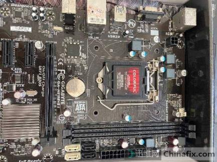
Machine board number: qiangwei mainboard IMBA-h610 H61
Fault phenomenon: Restart repeatedly
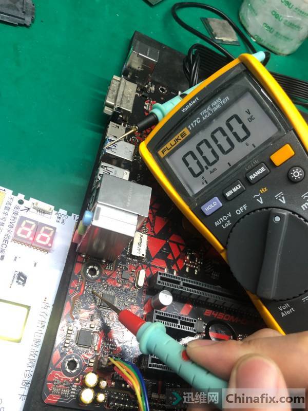
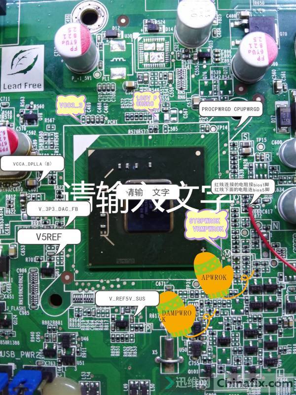
Maintenance process: Remove the motherboard and measure whether the CPU is powered or not. Other power supplies are normal, It seems that there is no CPU power supply, The CPU power supply chip is ISL6364, Measuring power supply is normal, oscilloscope measures SVID without waveform, CPU needs bridge to receive pwrok apwrok 25m crystal oscillator to start oscillation and read BIOS, and then send cpu procpwrgd signal, drampwrok is the prompt memory power supply sent by bridge to CPU, use oscilloscope to measure BIOS 1 foot found that bridge didn’t read BIOS at all, measure 25m crystal oscillator also has waveform, this motherboard doesn’t have drawings how to measure, try to disassemble H61 bridge from old motherboard first.
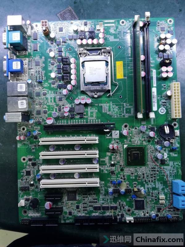
Repair of reverse push signal of main board of IPC Figure 1.
After the main board bridge was removed, I didn’t worry about welding the bridge, because I’m not sure it was the bridge problem. Although there were no drawings, the pin bitmap of the bridge could push back the signal, mark the signal test point outside and test again. As expected, after the bridge was replaced, the fault still remained. At this time,VCC propwrgd and no VCC pwrok were all normal,Why don’t you read the BIOS yet.
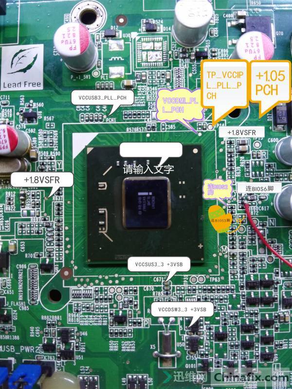
Repair of reverse push signal of main board of IPC Figure 2.
Repair of reverse push signal of main board of IPC Figure 3.
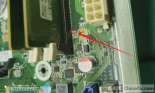
Later, it was found that when auto power off was powered on, the chip selection signal VCC of BIOS 1 pin was always the bottom. Why?
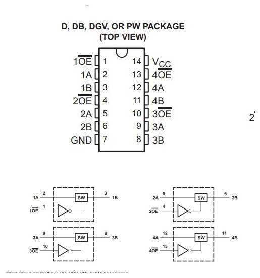
The ground Diode value is normal scanning circuit found that a 14 pin chip was connected. Looking up the PDF, it was found that this is similar to theGate circuitChip.
Repair of reverse push signal of main board of IPC Figure 4.
Repair of reverse push signal of main board of IPC Figure 5.
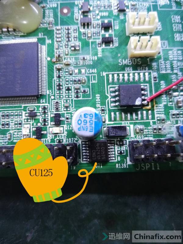
When powered on, BIOS 1 pin was connected to 11 pin of cu125. I removed the chip and measured that a was not VCC. After scanning the circuit, there was no connection anywhere. I estimated that it was in the bridge. After I removed BIOS and cu125, I found diode value OverLoad. I thought whether the line was broken with PCH, and there was no way to remove the bridge again.
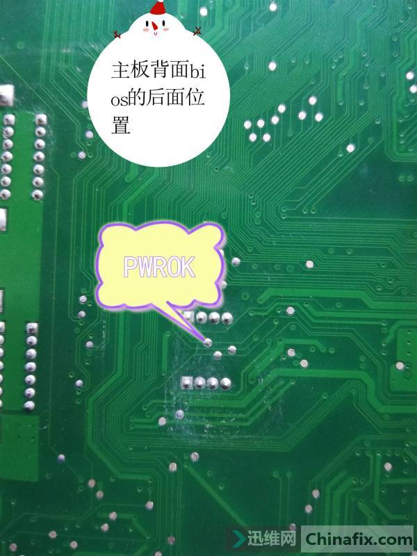
Repair of reverse push signal of main board of IPC Figure 6.
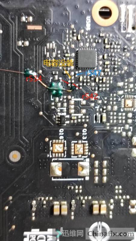
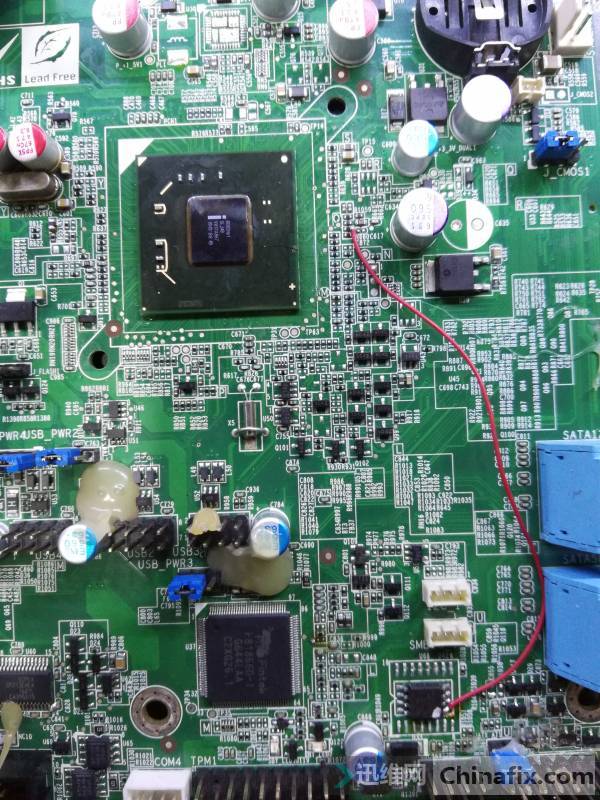
It was found that CS ා signal was connected to a resistor outside the bridge, but the resistance was not connected with cu125 12 pin or BIOS 1 pin. I wanted to connect the resistance with BIOS 1 pin.
This time, I didn’t rush to install the bridge. I wanted to measure all the VCC s of the bridge and connect them with those outside. In case the bridge lacks VCC, after marking, the bridge test CPU VCC came out, and the screen unexpectedly showed that booting up maintenance is over.
Repair of reverse push signal of main board of IPC Figure 7.
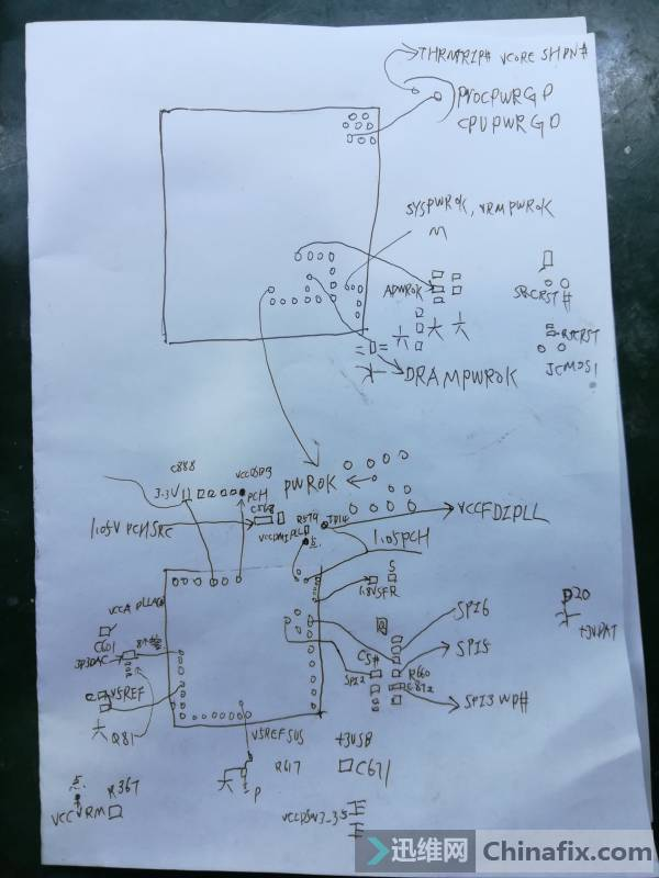
Repair of reverse push signal of main board of IPC Figure 8.