Address
304 North Cardinal
St. Dorchester Center, MA 02124
Work Hours
Monday to Friday: 7AM - 7PM
Weekend: 10AM - 5PM
Address
304 North Cardinal
St. Dorchester Center, MA 02124
Work Hours
Monday to Friday: 7AM - 7PM
Weekend: 10AM - 5PM
Troubleshooting of BIOS chip related video card
If the video card does not work, even though all necessary voltages (including 5V, 1.8V, VCore, Vmen, PEV power supply, etc.) are on the board, the problem may be in the BIOS.
If you experience problems reading BIOS firmware, the following symptoms will occur:
The video card does not work/its output is not initialized (if you try to start the computer with the video card connected to the monitor when you open it (it lights up briefly), it is likely that the problem is to use it with VRAM instead of BIOS);
The graphics card cannot be seen by the MATS diagnostic program;
The graphics card either works or does not work.
To check the performance of the flash BIOS of the graphics card, you need to:
Study the position of the pin responsible for power supply, startup and data exchange with GPU on the microcircuit body;
Find out the nominal value of the power supply voltage (1.8 or 3.3 V);
Use an oscilloscope to check whether it is exchanged with the video card core during initialization.
For example, the 4-Mbit Winbond 25Q40EWNIG chip installed on the back of the Zotac Nvidia GT1030 graphics card (item U501) is powered by 1.8 volts:
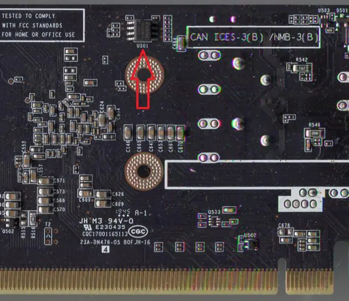
Troubleshooting of BIOS chip related video card Figure 1.
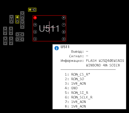
The pin assignment of W25Q40EW serial flash memory chip (packaged with 150mil SOIC-8):
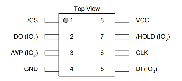
Troubleshooting of BIOS chip related video card Figure 2.
Pin assignment on W25Q40EW chip:
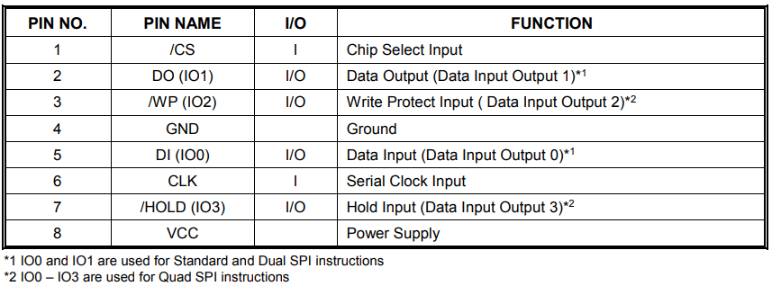
Troubleshooting of BIOS chip related video card Figure 3.
Before checking the BIOS chip, it is recommended that you at least have a general understanding of its working principle.
How to read the BIOS firmware when the video card is turned on?
The main function of BIOS chip on most modern devices is to use synchronous serial peripheral interface (SPI) protocol.
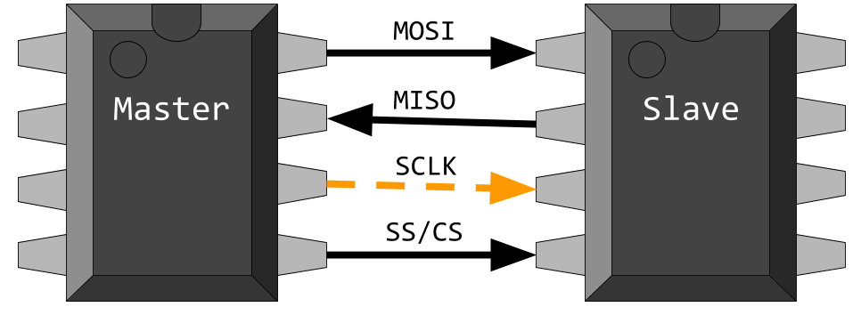
Troubleshooting of BIOS chip related video card Figure 4.
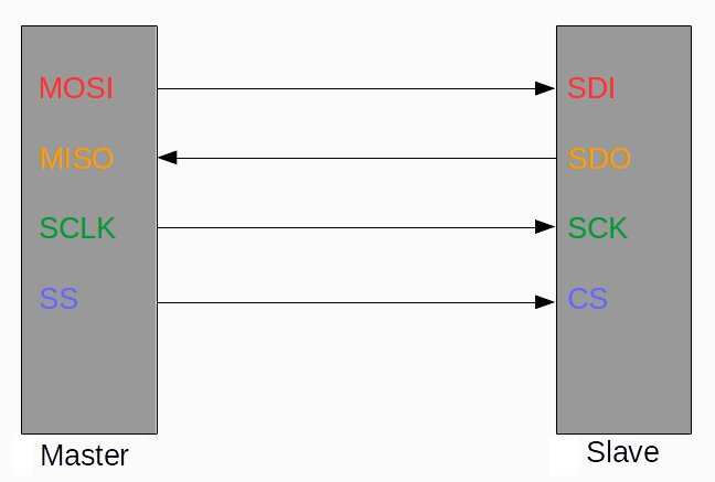
Flash BIOS chip performs duplex data exchange (simultaneously receiving and sending) through SPI protocol according to master slave principle.
Four communication lines (channels) are used to exchange data at a rate of 1 bit per cycle. The working principle is as follows:
In main aspects:
MISO – Output (master input and slave output);
MOSI – input (master output slave input);
SCLK — Serial Clock (CLK);
SS – Activated from the device (selected from the device).
In terms of slaves:
SDI – Input (from data input);
SDO – output (output from data);
SCK — synchronization signal CLK (serial clock);
CS – Activation signal (chip selection).
Troubleshooting of BIOS chip related video card Figure 5.
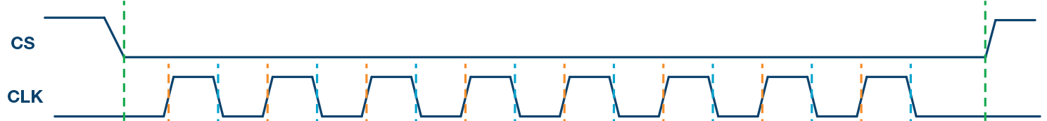
The synchronization signal is generated by the master device (on the graphics card GPU). It is used on the slave to determine when the data bit changes.
Example of signal waveform during data exchange with Winbond W25Q16BVSIG chip:
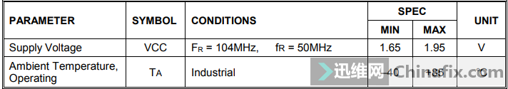
The W25Q40EW chip uses a clock signal with a frequency of F R up to 104 MHz to run almost all operations (and f R u003d 50 MHz):
Troubleshooting of BIOS chip related video card Figure 6.
Before the data exchange starts (when the graphics card is initialized), the GPU core sets the Chip Select pin (pin 1 CS or CE, Chip Enable) of the flash memory chip to the active state. It corresponds to the logic signal Low (for W25Q40EW, it is equal to zero volts in the range of – 0.5 to+0.59 V):
Troubleshooting of BIOS chip related video card Figure 7.
Then use the second and fifth outputs of the flash drive (W25Q40EW in this example) to start reading the BIOS firmware. It contains information about the video card name, core and memory frequency, voltage, and other important data.
Pin 2 (DO, data output in standard mode) of the flash BIOS chip is usually directly connected to the GPU, while pin 5 (DI, data input) is connected through resistance (usually 33 ohms on the Nvidia video card).
Diagram clip illustrating the BIOS flash drive connection on the GALAXY GT 1030 PG110-A00 P85C Rev V10 video card:
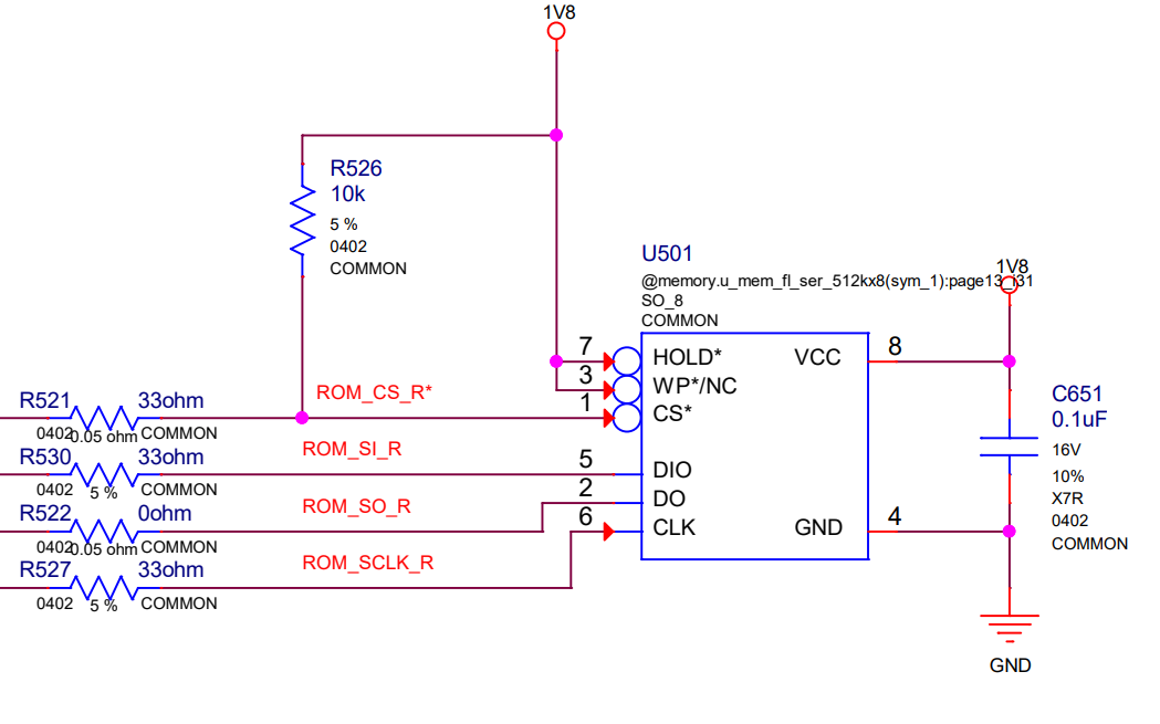
Troubleshooting of BIOS chip related video card Figure 8.
The BIOS chip binding resistors connected to pins 1, 5, and 6 are usually located near the housing of the GPU (sometimes on the other side of the board).
After understanding the purpose of SPI Flash BIOS chip pin, you can perform actual verification.
How to check the health of the BIOS chip on the video card?
When checking the performance of W25Q40 series SPI BIOS microcircuits, first check the power supply voltage VCC/VDD (1.8 or 3.3 V) of its eighth output and whether there is a CS signal on the first pin.
Check the CS signal on the flash BIOS chip of ASUS GeForce GTX 1060 graphics card:
Troubleshooting of BIOS chip related video card Figure 9.
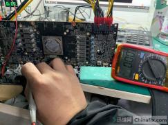
Then, use the oscilloscope to check if there is any exchange on pins 2 and 5 when initializing the video card.
If the video card is not activated and does not try to read information from it when it is turned on, then either it has entered another world or the video card has not entered the initialization stage for some reason (for example, the resistance connected between the BIOS chip and the GPU core is faulty).
If the receive and send pins (DI and DO) of the flash BIOS have signals, but the graphics card does not work, the BIOS chip is faulty, or its firmware is damaged (it may be an error in modification or an inappropriate BIOS).
In this case, you need to use the programmer to refresh the correct BIOS firmware. If the BIOS chip has no signs of life, you can replace it with a chip of the same or larger capacity, with the appropriate clock frequency and the same power supply voltage (VCC).
If the BIOS chip works, the correct firmware is loaded, and the oscilloscope displays the exchange between the core and the flash drive during initialization, but the graphics card still does not work, then the reason is likely to be memory failure and/or GPU.